1.
2.
3.
1.
2.
3.
1.
1.
2.
3.


| ATTENTION to USAGE for Ultra High Voltage Ceramic Power Resistors | |
| To obtain optimum performanc of our resistors, the following deserves full attention. | |
| 1. | Overall Attention |
| (a) | Reduction Ratio of Rated Power: |
| In applications where the ambient temperature exceeds 25 °C or the resistor is exposed to thermal radiation, the rated power must be reduced to be within the derating curve. | |
| (b) | Application with Impulse Voltage, Transient Voltage, Intermittent Overload or pulse Load: Under such conditions, Designing based on the stationary state or average electric power alone must be disregarded. |
| (c) | Handling: |
| . | The resistor is made of ceramic. Attention must be paid not to inadverently drop or hit the ceramic resistors |
| 2. | Attention to Respective Resistors: |
| (a) | CE type: |
|
1.
|
For long time use, keep the surface temperature of the resistor at 100 °C maximum. The CE type has a tendency to increase in resistance. |
|
2.
|
Resistance value 10K |
|
3.
|
Resistor of 100 |
| (b) | GS type: |
|
1.
|
GS type will not tolerate surge voltage, and cannot be used with impulse voltage exceeding the specifications. |
|
2.
|
If the resistor is water cooled, the water quality must be checked. Pure water is recommended. |
|
3.
|
The surface is coated with glass film to maintain the characteristics at a surface temperature as high as 300°C or higher. However, the dielectric strength will decrease at this temperature. |
| (c) | DC type: |
|
1.
|
DC type is not suitable for continous load. Good for short term load only. |
| (d) | RH type: |
|
1.
|
When used as charge or discharge resistor, reduce voltage by means of voltage reduction ratio in consideration of time constant. |
|
2.
|
Compared with CE Type, RH type has smaller injection energy capacity due to the nature of film resistors. |
|
3.
|
RH type is inductive due to the helical-cutting design of film resistor for higher resistance. |
| VOLTAGE REDUCTION RATIO with IMPULSE WAVEFORM: | |
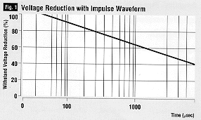
| Withstand voltage will change with time constant or wave tail duration on the basis of the standard impulse voltage. Fig. 1 represents the withstanding voltage reduction ratio versus time with 1.2 x 50 µ s waveform is defined as 100%. | |
 |
|
| POWER DERATING with PARALLEL RESISTORS COMBINED TOGETHER: | |
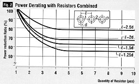
| CE, GS & RH resistors, when used in parallel, will radiate heat between each other. The reduction ratio shown in Fig. 2 is to be noted. | |
 |
|
| home page | product guide | CE/CH | GS | DZ Type | DS/DC |